This portfolio showcases my previous work in PCB design and fabrication. It includes pictures of various PCBs that I have designed and fabricated using PCB Designing tools.
This portfolio includes pictures of the following PCBs that I have designed and fabricated:
- Home Automation PCB
- Motor driver circuit
- UWB Based Circuit Board
- ATtiny Ultra Low powered 7-segment LED clock
- Automotive grade CANBUS ckt
- And more! (Honestly, at this point I lost count and my drive is a jungle of half-documented PCBs—sometimes I’m just as surprised as you’ll be! I might need a time machine to recall why I ever built them!)
- Highspeed PCB Design Commming Sooonnnnnn!!!!!!!
Read my article where I've used Clever design practices and how I optimize the Power Density Across the Board:
[1] A. Shahriar, Anik, M. H. (2025). CHIGLU: A Modular Hardware for Stepper Motorized Quadruped Robot—Design Approach and Analysis. MethodsX, 103270. https://doi.org/10.1016/j.mex.2025.103270
My skills in PCB design and fabrication include:
- Designing and routing PCBs, transitioning progressively to Altium.
- Knowledge of PCB layout design principles
- Creating custom footprints for components
- Generating Gerber files for fabrication
- Selecting appropriate components and connectors for specific applications
- Soldering and assembling PCBs
- Familiarity with various fabrication techniques such as SMT and through-hole assembly
- Design for Manufacturing
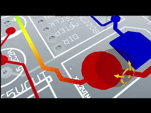
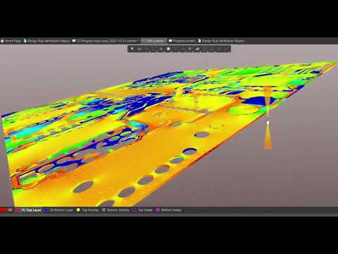
| Voltage Drop Analysis (Click to play) | Current Density Analysis (Click to play) |
|---|---|
 |
 |
Here are the pictures of my previous PCB design and fabrication work:
 |
 |
 |
 |
|
|
 |
 |
 |
 |
 |
 |
|
 |
 |
 |
 |
 |

Currently tackling this issues for this project and solving:
Sensor Replacement: Modify the schematic and PCB layout to remove the existing accelerometer and integrate the Diodes AH1912 Hall-effect sensor.
Motor Control Circuit Integration: Ensure the hardware connections between the STM32L011 microcontroller and the DVR8838 motor driver are correctly implemented.
Battery Management Circuit Verification: Verify the existing circuitry for the MAX17048 battery monitor.
Low power design optimization: Analyze the schematic for potential physical current leakage paths to ensure the hardware design can achieve ultra-low power targets.
Please feel free to contact me.
Email: abidshahriar97@gmail.com
Due to time limitation I haven't added each PCB's features and specifications, but as I am growing, expaninding and doing my best, I'm freelancing on Fiverr. Check Fiverr Portfolio here: https://www.fiverr.com/users/ryker007/portfolio
Also here: