Switching document languages : 日本語, English
- Open source software/firmware that turns the AVR-DU family into a USB-connected programmer.
- Capable of reading, erasing, and writing NVM (non-volatile memory) for UPDI, TPI, PDI, and ISP* type AVR series devices.
- AVRDUDE is assumed as the programming application on the Host PC. It looks like "PICKit4" or "Curiosity Nano".
- Equipped with VCP-UART transfer function.
- All results are distributed under the MIT license.
- ISP (i.e. Low-Voltage SPI control) support is provisional.
The conventional USB4AVR is designed to use a USB-serial conversion circuit, but this UPDI4AVR-USB is a complete single-chip design that uses the USB peripheral circuit built into the MCU.
1.35.53 (26/08/30)
- During ISP control, an external clock for XTAL1 can be output on PA6.
1.35.52 (26/08/28)
- Compatible with
euboot3.72.50 - Fixed ISP control
The pre-built binaries can be uploaded to the "AVR64DU32 Curiosity Nano : EV59F82A" product for easy setup.
A story from a little while ago
The existence of the AVR-DU family was announced in the spring of 2021, but was soon put on hold. While that was stalled, the AVR-Ex series was released first, and after some time, the first production AVR64DU32 (with unfortunate errata) was finally released in May 2024, and the release of the remaining 14P/20P products was confirmed in October.
The biggest feature is that it is the only AVR-Dx series family to have built-in USB 2.0 "Full-Speed" device peripheral functions. This is a function inherited from the ATxmega AU family (expensive and minor), and is much more powerful than that of the ATmega32U4 family. The AVR-DU family also has SOIC-14P and 3mm square VQFN-20P packages, and can be made compact, so it has great potential.
On the other hand, since it is such a new product, open source compatibility has not progressed. The official development environment is MPLAB-X, but because of the lavish build environment based on HAL, it takes up a very large amount of flash capacity. Moreover, the throughput is not sufficient. Do you want to cook a crucian carp with a battle axe?
What I wanted first from the AVR-DU family was the realization of VCP transfer based on USB-CDC/ACM that is normally recognized by the OS, and UPDI/TPI programming function based on USB-HID that can be handled from AVRDUDE. It naturally has to be a USB composite device. On the other hand, I am not considering using it from MPLAB-X due to licensing issues. So I will forget about the existence of dWire and OCD.
The only documents that provide clues are the USB-IF public specification, the AVR-DU family data sheet, and the ATxmega AU family manual. This is a completely clean room development. I started by building a USB protocol stack from scratch using only AVR-GCC and AVR-LIBC, without any involvement in other projects. I condensed the main operations of the USB composite device to about 3KiB, and it took me 20 days to make it freely applicable. (Of course, I can also make a DFU bootloader, but that's a different plan.)
Next, I investigated the AVRDUDE source code "jtag3.c". It was not difficult because I had already contributed to the improvement of "jtagmkII.c" and "serialupdi.c". I was familiar with most of the UPDI NVM control from hand-making the UPDI4AVR series, and I have also been involved in supporting the AVR-Dx/Ex series. When I first created an emulator application that imitated the response of "Curiosity Nano", I ran into a problem where I could not freely change the USB-VID:PID, so I had to strengthen "usb_hidapi.c". In addition, since it only required adding a small amount of code, I was able to handle not only UPDI devices but also TPI devices. This is where my experience of hand-making TPI4AVR came in handy.
It took 10 days to create a scenario and get it to work, and another 20 days to check the operation of more than 20 types of UPDI devices I had on hand and get a result that I was fully satisfied with. But more than that, it's tedious time to prepare the outline!
Finally, I'm releasing the first open source branch that can be used for "AVR64DU32 Curiosity Nano : EV59F82A". It should be fine for trying it out for general use.
It is mostly a replacement for the traditional JTAG2UPDI and microUPDI. If you are already using them, you can start using it right away.
This software can:
- Only install on the AVR-DU family.
- Operates all released UPDI type AVR series:
- All tinyAVR-0/1/2, megaAVR-0, AVR-Dx, AVR-Ex, AVR-Lx, AVR-Sx products
- Operates all released TPI type ATtiny series:
- ATtiny4 ATtiny5 ATtiny9 ATtiny10 ATtiny20 ATtiny40 ATtiny102 ATtiny104 (8 types in total)
- Operates (probably) all released PDI type ATxmega series:
- Operation has been confirmed only for ATxmega128A4U.
- PDI support is enabled by default only when built for "Curiosity Nano". (Uses a different wiring from UPDI/TPI)
- Supports ISP control for select classic AVR models.
- Models currently confirmed to work include the ATmega328P, ATtiny13/85, etc.
- No additional driver installation is required because it uses the standard OS driver for Windows/macos/Linux. VID:PID can be customized with EEPROM.
- If additional drivers/Inf files are already installed, the device vendor that matches the VID:PID will be displayed. (Be careful of license infringement)
- Includes VCP (Virtual Communication Port) based on the CDC-ACM specification.
- A push switch can be used to reset the target device while the VCP is running.
- The reset state is maintained while the switch is pressed. Disabled while a UPDI/TPI program is running.
- Even target devices (UPDI type) that do not have a hardware reset terminal as standard, such as the tinyAVR series, can be reset without turning off the power.
- Useful for forcibly restarting application code such as boot loaders written to the device. Compatible with Arduino IDE.
- Can lock and unlock the target device. (LOCK bit FUSE operation and forced chip erase)
When using hardware (MCU board) designed specifically for this software, you can do the following:
- Supports two types of UPDI type high voltage writing. Requires additional dedicated hardware circuitry.
- Supports one type of TPI type high voltage writing. Requires additional dedicated hardware circuitry.
This software cannot:
- Does not work with devices other than the AVR-DU family, as they do not have the necessary and compatible USB peripherals.
- Porting to the ATxmega AU family is probably possible, as the USB peripherals are similar. (No plans: Fork required)
- Supports USB 2.0 "Full-Speed" only. The AVR-DU family does not support "High-Speed". (Not possible)
- Support for ISP-type classic AVR devices is limited to a select range of relatively popular models.
- PP/HVPP-type devices are not supported; due to differing hardware requirements and a lack of GPIO compatibility, they would require separate software (necessitating a fork).
- JTAG communication, SWD/SWO, dWire, and OCD functions are not supported. (No plans)
- High voltage programming is not supported because the 14P package product (AVR16-32DU14) does not have any extra pins. 20P/28P/32P package products are required.
- DEBUG build (PRINTF) cannot be used because there are insufficient pins in 14P/20P and no free space in 16KiB models.
Below is a simple usage example for "AVR64DU32 Curiosity Nano". This product series can be mounted on a breadboard without soldering using the included pin headers.
Tip
We recommend installing an additional LED1 (active-high) between PF3 and GND. LED0 corresponds to the onboard LED connected to PF2. Except for the Curiosity Nano, LED0 is typically connected to PC3 and LED1 to PD3; both are controlled using active-high logic.
The standard wiring configuration when connecting the device is shown in the diagram below. This layout is common to all models, with the exception of the 14-pin package, which has a limited number of pins.

While idle, pins PA0, PA1, PA2, and PA3 function as open-drain I/Os with internal pull-up resistors. Notably, the PA2/PA3 pair serves as the VCP-TxD/RxD interface; LED1 illuminates when the signals on these two pins differ (XOR logic). This allows you to perform "LED blink" experiments on the target device without adding any external components.
Tip
Since the PA2 (VCP-TxD) pin uses an open-drain output configuration, it will not conflict with the target device's I/O settings, regardless of how they are configured. As shown in the wiring diagram, this pin corresponds to the SCK pin in ISP mode, effectively controlling the standard "D13" LED. The maximum VCP communication speed is 500 kbps, a limit imposed by the Curiosity Nano's onboard debugger (PKOBN—PicKit On-Board Nano); however, speeds several times higher than this are achievable if using a bare-chip implementation.
For UPDI control, the target device requires three wires: "VCC", "GND", and "UPDI (TDAT)". Optionally, three more wires can be added: "nRST (TRST)", "VCP-TxD", and "VCP-RxD". Unless the device sets the GPIO to push-pull output, all connections are open-drain with built-in pull-up resistors. If you are concerned about GPIO contention, you can insert a 330Ω series resistor.
The electrical characteristics are based on 5V/225kbps, and you should pay attention to the slew rate in the range of VCCx0.2 to 0.8.
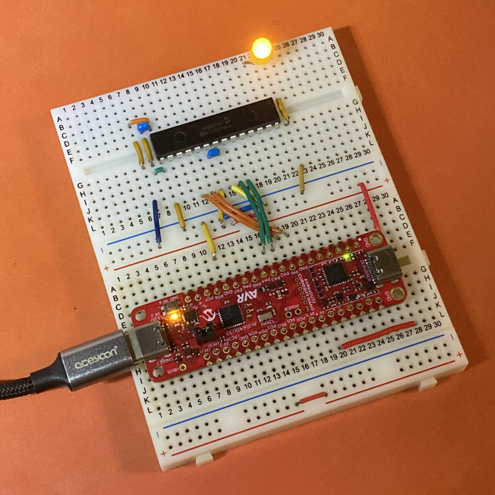

The following signal arrangement is recommended for converting to the AVR-ICSP MIL/6P connector. This is compatible with TPI control and two types of HV control methods. (However, HV control is not possible without a dedicated circuit.)

If the target device is AVR64DU28, a minimum connection test can be performed with the following command line.
avrdude -P usb:04d8:0b15 -c pickit4_updi -p avr64du28 -v -U sib:r:-:rTip
The -Pusb:vid:pid syntax is available in AVRDUDE>=8.0, but not earlier.
To use with AVRDUDE<=7.3, you must store the VID:PID required by the -c option in EEPROM.
Avrdude version 8.2-20260803 (23f4caed)
Copyright see https://github.com/avrdudes/avrdude/blob/main/AUTHORS

System wide configuration file is /usr/local/etc/avrdude.conf
User configuration file is /Users/user/.avrduderc

Using port            : usb:04d8:0b15
Using programmer      : pickit4_updi
AVR part              : AVR64DU28
Programming modes     : SPM, UPDI
Programmer type       : JTAGICE3_UPDI
Description           : MPLAB(R) PICkit 4 in UPDI mode
ICE HW version        : 0
ICE FW version        : 1.34 (rel. 49)
Serial number         : MX********
Vtarget               : 5.02 V
PDI/UPDI clk          : 225 kHz

Partial Family_ID returned: "AVR "
Silicon revision: 1.3

AVR device initialized and ready to accept instructions
Device signature = 1E 96 22 (AVR64DU28)
Reading sib memory ...
Writing 32 bytes to output file <stdout>
AVR     P:4D:1-3M2 (A3.KV00S.0)
avrdude done. Thank you.For TPI control, the target device requires five wires: "VCC", "GND", "TDAT", "TCLK", and "TRST". As a result, for the 6P device ATtiny4/5/9/10, only one unused pin remains. All connections are open drain with built-in pull-up resistors (approximately 35kΩ).
Note that VCC must be supplied with 4.5V or more in order to rewrite the NVM. 3.3V is fine if you are only reading the memory contents.
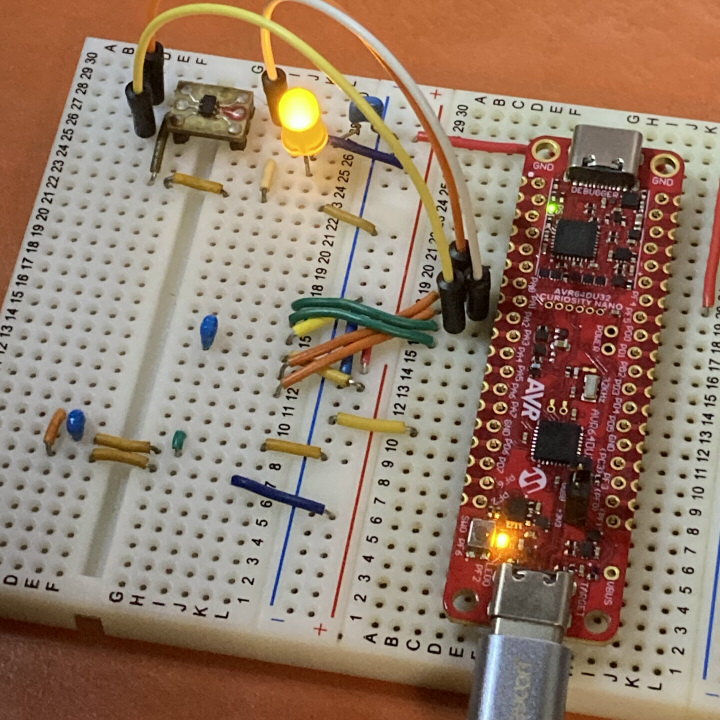

If the target device is ATiny10, a minimum connection test can be performed with the following command line.
avrdude -P usb:04d8:0b15 -c pickit4_tpi -v -p t10 -U flash:r:-:IAvrdude version 8.2-20260803 (23f4caed)
Copyright see https://github.com/avrdudes/avrdude/blob/main/AUTHORS
System wide configuration file is /usr/local/etc/avrdude.conf
User configuration file is /Users/user/.avrduderc
Using port : usb:04d8:0b15
Using programmer : pickit4_tpi
AVR part : ATtiny10
Programming modes : TPI
Programmer type : JTAGICE3_TPI
Description : MPLAB(R) PICkit 4 in TPI mode
ICE HW version : 0
ICE FW version : 1.34 (rel. 49)
Serial number : MX********
Vtarget : 5.00 V
AVR device initialized and ready to accept instructions
Device signature = 1E 90 03 (ATtiny10)
Reading flash memory ...
Reading | ################################################## | 100% 0.26 s
Writing 86 bytes to output file <stdout>
:200000000AC011C010C00FC00EC00DC00CC00BC00AC009C008C011271FBFCFE5D0E0DEBF02 // 00000> .@.@.@.@.@.@.@.@.@.@.@.'.?OeP`^? flash
:20002000CDBF02D016C0ECCF48ED50E04CBF56BF4FEF47BB7894619A0A9ABA98029A4FEF35 // 00020> M?.P.@lOHmP`L?V?OoG;x.a...:...Oo
:1600400059E668E1415050406040E1F700C00000F5CFF894FFCFAB // 00040> YfhaAPP@`@aw.@..uOx..O
:00000001FF
Avrdude done. Thank you.In this example, the blinking LED sketch binary for the PB2 terminal is read.
If you want to pull out the UART of the ATtiny102 and ATtiny104 to the 6P connector and connect it to the VCP, you will need to use some ingenuity. PA0/TCLK and PB3/RXD must be shorted, and PA0 must be left as an unused GPIO in principle.
PDI control, which is mainly used in the ATxmega series, requires special considerations that are different from UPDI and TPI.
- All PDI-compatible devices have an absolute rating of 3.5V or less. Therefore, all signal lines, including VTG/VCC, must be 3.3V reference.
- Although the PDI_DATA line is a single-wire communication, it must be controlled by the push-pull method. Since PoR has a built-in pull-down resistor of 22kΩ by default, the PDI activate operation must first pass a current that overcomes this. This cannot be achieved with an open-drain circuit such as UPDI/TPI.
- The PDI_CLK line also serves as a hard reset signal, and must be controlled by the push-pull method to increase speed.
When using "AVR64DU32 Curiosity Nano", you must first update the debugger firmware to the latest version using MPLAB-X. As of at least 1.31 (rel. 39), you can use the -xvtarg=<dbl> option to permanently change the voltage of the VTG/VCC terminal output next to the PF4 terminal to one of 5.0, 3.3, or 1.8.
avrdude -c pkobn -p avr64du32 -x vtarg=3.3Changing target voltage from 5.00 to 3.30V
Avrdude done. Thank you.This must be done before wiring up the target device, and you must ensure that the state is saved correctly even after powering off, as older firmware does not remember this setting permanently.
Changing target voltage from 3.30 to 3.30V
                             ^^^^
Once the above setup is done correctly, you can safely connect the following wires to your PDI target device. You need at least four wires: "VCC", "GND", "PDAT", and "PCLK". You can optionally add two more wires: "VCP-TxD" and "VCP-RxD".
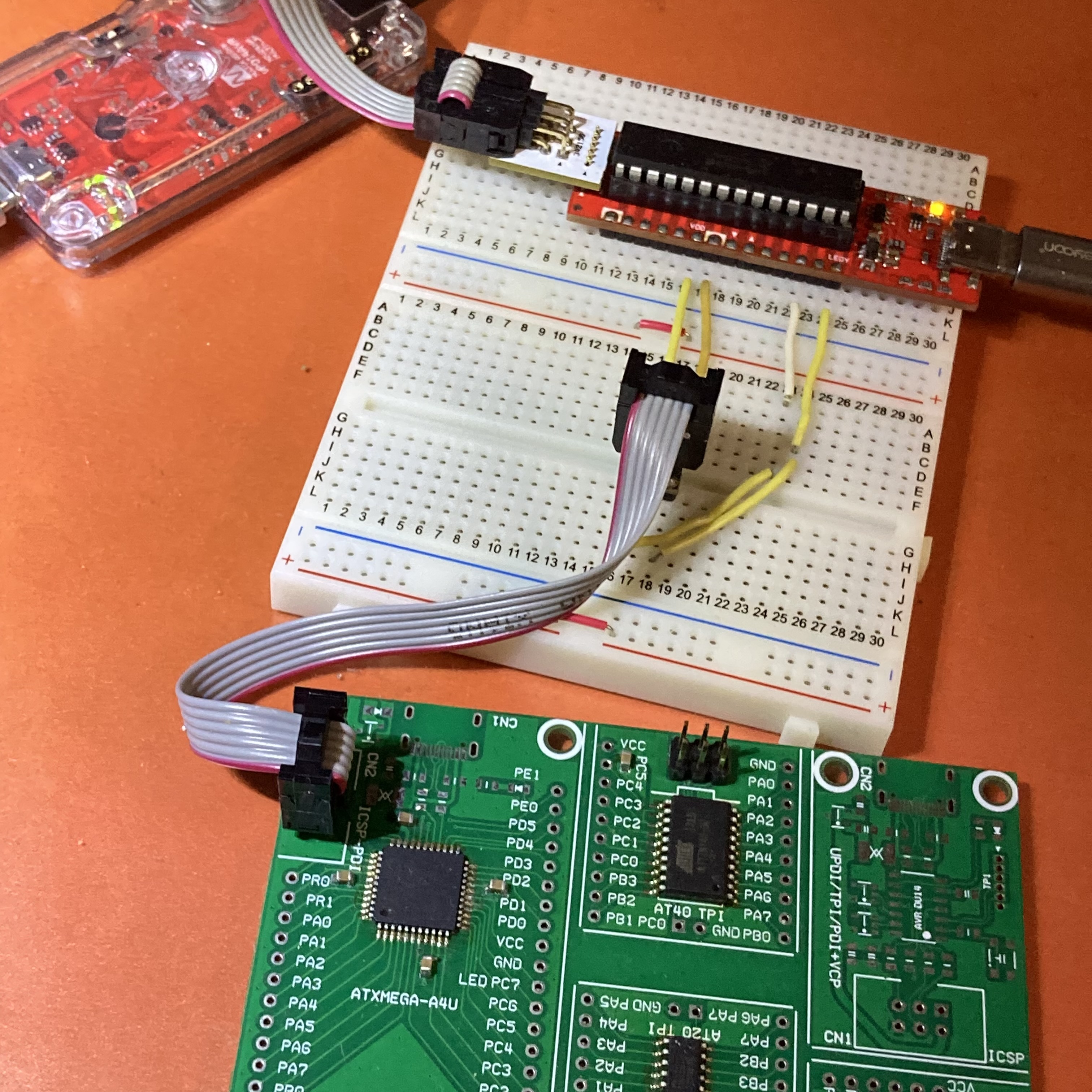

avrdude -P usb:04d8:0b15 -c pickit4_pdi -p x128a4u -v -U prodsig:r:-:IAvrdude version 8.2-20260803 (23f4caed)
Copyright see https://github.com/avrdudes/avrdude/blob/main/AUTHORS
System wide configuration file is /usr/local/etc/avrdude.conf
User configuration file is /Users/user/.avrduderc
Using port : usb:04d8:0b15
Using programmer : pickit4_pdi
AVR part : ATxmega128A4U
Programming modes : SPM, PDI
Programmer type : JTAGICE3_PDI
Description : MPLAB(R) PICkit 4 in PDI mode
ICE HW version : 0
ICE FW version : 1.34 (rel. 49)
Serial number : MX********
Vtarget : 3.30 V
PDI/UPDI clk : 2500 kHz
Silicon revision: 0.0
AVR device initialized and ready to accept instructions
Device signature = 1E 97 46 (ATxmega128A4, ATxmega128A4U)
Reading prodsig/sigrow memory ...
Reading | ################################################## | 100% 0.01 s
Writing 64 bytes to output file <stdout>
:200000000D40740B403FFFFD334132363233FFFF11FF0E0003004933FFFFCF072440FFFF87 // 00000> .@t.@?.}3A2623........I3..O.$@.. prodsig
:20002000440400FF0000FFFFFFFFFFFFFFFF4B09FFFF8301FFFF0409FFFFFFFFFFFFFFFFA8 // 00020> D.............K.................
:00000001FF
Avrdude done. Thank you.Tip
To write NVM to a TPI device, you need to reset the VTG voltage to 5.0V. UPDI devices work fine at both 5.0V and 3.3V, but some devices have a serious errata that significantly reduces the NVM rewrite life at 3.3V, so be careful.
Note
When PDI support is enabled, the UPDI4AVR-USB software size exceeds 14KiB. Therefore, it cannot coexist with the USB bootloader (euboot 2.5KiB) on AVR16DUxx. For this reason, PDI support is only enabled in builds for "AVR64DU32 Curiosity Nano", which definitely has ample memory capacity. In reality, only a limited number of users need PDI control, so it would be more meaningful to use "CNANO" on an as-needed basis rather than preparing dedicated hardware that cannot be used for other purposes.
As of version v1.35.50, limited support is provided for the 6-wire ISP control method common to classic AVR microcontrollers. However, given the vast number of chip variants using this programming method—many of which are no longer easily available or exist only as unofficial, low-quality clones—it is impossible to cover them all. Current ISP control support is subject to specific operational conditions:
- Limited to Low-Voltage SPI communication; operating voltage range is 2.7V to 5.5V.
- Testing has been conducted only on relatively popular models, such as the ATtiny13/85 and ATmega328P.
- Control is not possible if fuse settings result in a low default startup frequency; 8MHz or higher is recommended. Incorrectly setting fuses—such as requiring an external oscillator—can immediately "brick" the device.
- Operation with significantly older models, such as the AT89 series, is not supported.
- If control fails, some supported models may attempt to switch to high-voltage (12V) debugWire control; however, this mode is not currently supported.
- Naturally, if incorrect fuse settings render the device uncontrollable, the inability to use high-voltage control means there is no way to recover the device.
The ISP wiring requires six lines: VCC, GND, MOSI, MISO, SCK, and RESET. The pin assignments and wiring for the ICSP-6P connector are identical to those used for UPDI/TPI. This means that if MISO and SCK are configured (e.g., via the SoftwareSerial library) to function as TxD and RxD—or if the lines are bridged—VCP-UART communication becomes possible.
Tip
Starting with version 1.35.53, functionality has been expanded to allow PA6 to output an external clock signal for XTAL1/CLKI (default: 2 MHz). This makes it possible to recover a "bricked" device caused by an incorrect operating clock setting in the LFUSE.
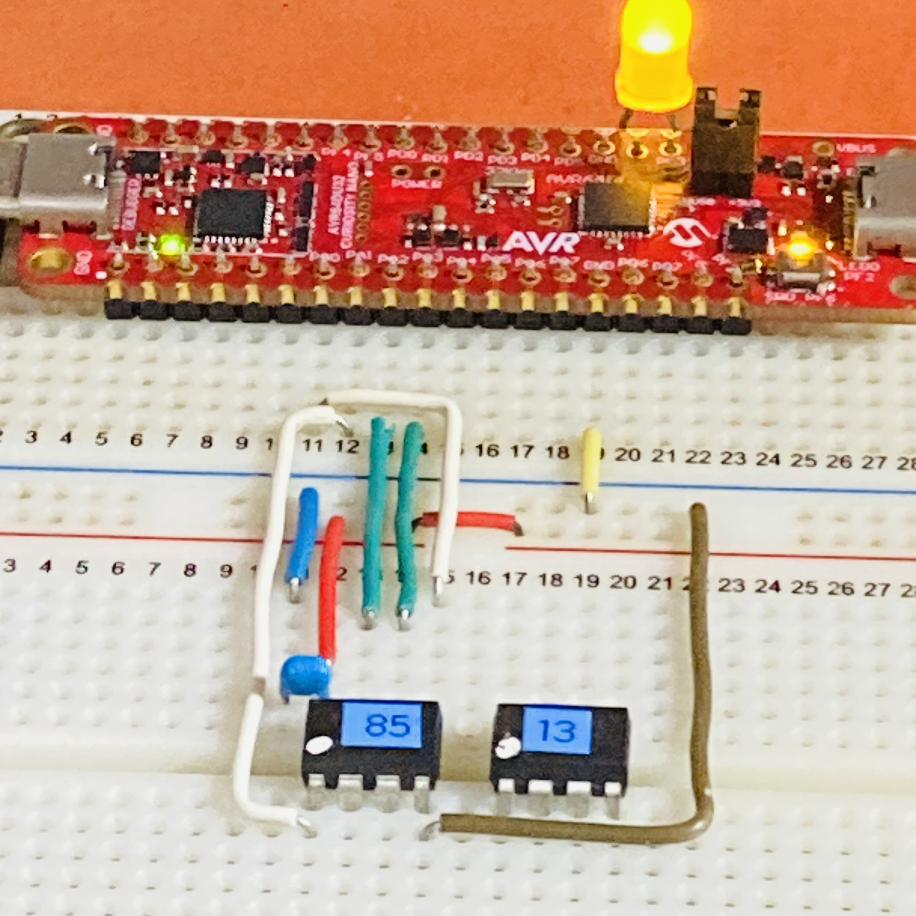

Programmer selection IDs such as pickit4_isp, xplainedmini, atmelice_isp, and snap_isp can be used.
avrdude -P usb:04d8:0b15 -c pickit4_isp -p m328p -v -U prodsig:r:-:ITip
The control speed (in kbps) can be specified using the -B option within a range of 1000 to 1 (default: 200). However, setting the frequency too low is impractical, as it conflicts with timeout requirements.
While AT89Sx series devices use active-high logic for external RESET, a known issue prevents AVRDUDE from providing the necessary device information to control this pin. This can be resolved by installing an inverting gate IC (inverter) on the external RESET line.
LED0 shows several expressions depending on the situation.
- Heartbeat - or deep breath. USB connection established with Host OS. Ready for use.
- Short flash - Waiting for USB connection. Not seen by Host OS.
- Long blink - SW0 is pressed down. Not programming. Target device is resetting (if possible).
- Short blink - Programming in progress. VCP communication is disabled.
By including an additional LED1, it is also possible to indicate VCP communication activity.
In progress. A dedicated control circuit must be attached externally. Technically, this has already been achieved in the previous version UPDI4AVR (USB serial communication version).
Currently, two prototypes are in progress.
- All-in-one model in FRISK (candy) case size. Standard design of UPDI4AVR-USB.
- Dedicated expansion board model that mounts "AVR64DU32 Curiosity Nano" as a daughter board.
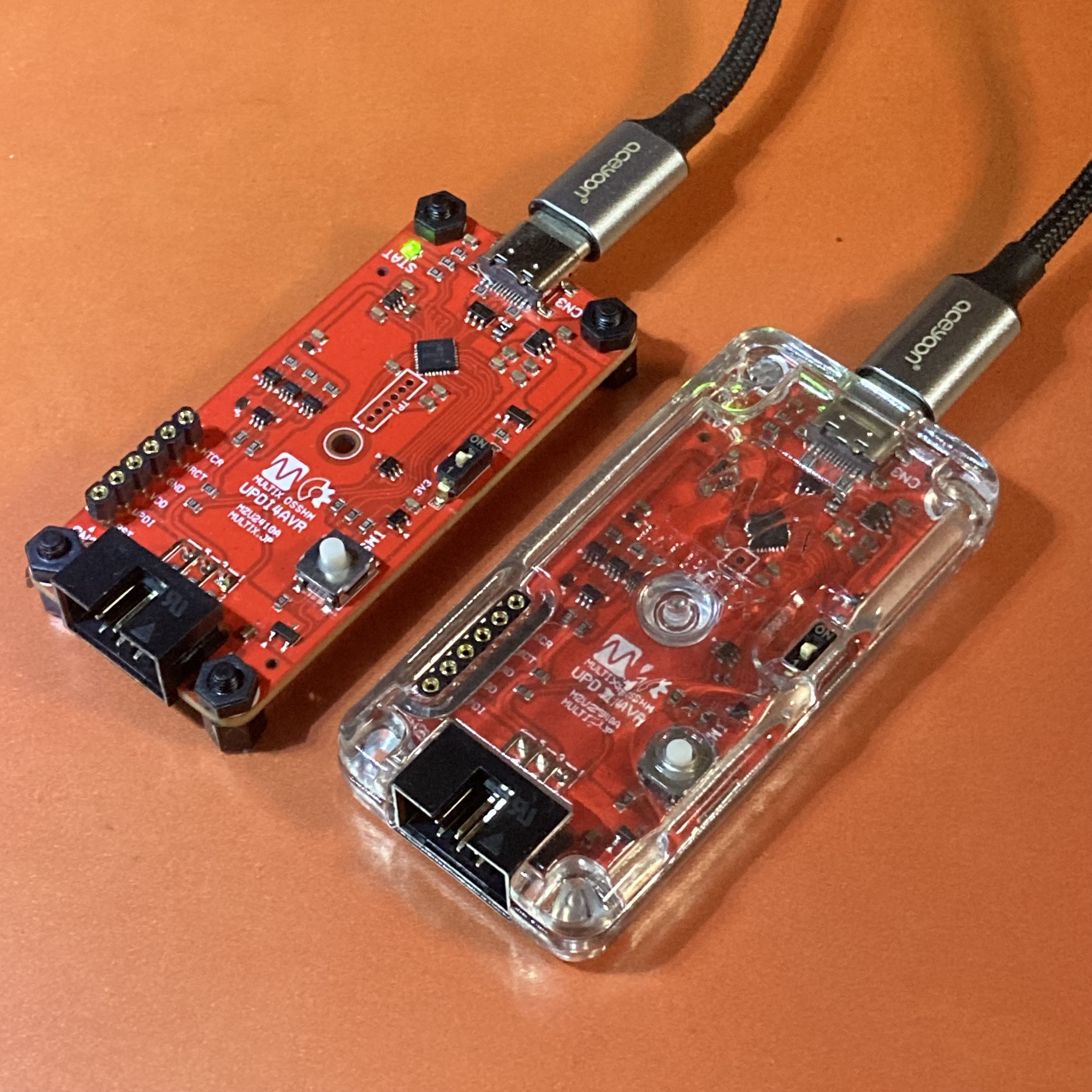

There are two ways to enable HV control.
- Select
-cpickit4_updiand add-xhvupdioption. This method is only possible with this-cprogrammer selection. - Execute the AVRDUDE command while holding down
SW0(or SW1). The-coption is optional. This is the only method by which HV control mode can be enabled for TPI devices. - There is also a method to apply a patch to AVRDUDE that enables
-xhvtpispecifically for this software, but this is not a common method. (For industrial production sites)
Tip
There are no PDI devices that require HV control.
Note
The hex/variants folder contains a Makefile for use with Arduino CLI. You can use this to generate Hex and Fuse files corresponding to the preset HAL profiles.
The hex/updi4avr-usb folder contains precompiled Hex files for the Curiosity Nano.
The hex/test-blink folder contains the Hex file and source code for a "blink" test on the target device.
By installing the SDK at the following link into the Arduino IDE, you can easily build and install for all AVR-DU family chips, including bare metal chips.
For build options, see <UPDI4AVR-USB.ino>.
For intermediate to advanced users: Here is a brief overview of the setup process using Arduino CLI.
For details, please refer to [Arduino CLI].
For Windows:
@rem "Arduino-CLI install for Windows"
winget install ArduinoSA.CLI
For Linux/macOS:
# Arduino-CLI install for Linux/macOS
brew update
brew install arduino-cli
Alternatively:
curl -fsSL https://raw.githubusercontent.com/arduino/arduino-cli/master/install.sh | sh
Installing the MultiX Zinnia Product SDK [modernAVR]:
arduino-cli core install MultiX-Zinnia:modernAVR --additional-urls https://askn37.github.io/package_multix_zinnia_index.json
Checking the list of build options:
arduino-cli board details -b MultiX-Zinnia:modernAVR:AVRDU_noloader
Compilation test for UPDI4AVR-USB:
arduino-cli compile UPDI4AVR-USB.ino -b MultiX-Zinnia:modernAVR:AVRDU_noloader
From version v1.35.49 onwards, you can preload a custom HAL (Hardware-Architecture-Layout) configuration file—located in the HAL directory—by creating a usrdef.h file in the src directory. This allows you to define or modify arbitrary environment variables directly from the Arduino IDE (similar to the functionality available in Arduino CLI).
/* usrdef.h example */

#undef F_CPU
#undef NDEBUG
#undef DEBUG
#undef CONSOLE_BAUD
#undef LED_BUILTIN
#undef SW_BUILTIN

#define F_CPU 20000000UL
#define DEBUG 1
#define CONSOLE_BAUD 500000UL
#define LED_BUILTIN PIN_PC3
#define SW_BUILTIN PIN_PF6

#define HAL_PROFILE "HAL/XXXXXXXX.h"
If the usrdef.h file is missing (the default state), the system proceeds as before: it references macros such as __AVR_AVRXXXX__ to select and load the appropriate preset.
Of course, you are also free to create your own custom HAL profile and place it in the HAL directory. In that case, it is recommended to use an existing AVRDU_xxP.cpp/h file—corresponding to the number of enclosure pins you are using—as a template.
Tip
Since usrdef.h is excluded via .gitignore, it will not be accidentally published. This mechanism was originally intended for handling personal configuration data and similar information within the sketch folder.
When using Arduino-CLI, you can configure more detailed settings by creating or editing the project file sketch.yaml.
By storing a custom USB VID:PID pair at the beginning of its EEPROM area, the USB4AVR-USB allows you to change the default programmer ID used when the -Pusb:... option is omitted. This feature is useful in the following scenarios:
- When you want to match the implicit programmer selection used by the Arduino IDE or various SDKs.
- When you want to connect and use multiple programmers/debuggers simultaneously on a single Host PC.
The VID:PID is changed using another programmer or debugger (not the USB4AVR-USB itself) with a command syntax like the following:
avrdude -c pkobn -p avr64du32 -U eeprom:w:0xEB,0x03,0x77,0x21:mCaution
Since VID:PID pairs are proprietary to specific vendors, please be mindful of potential rights infringement. On Windows, in particular, these values influence implicit driver selection.
The USB4AVR-USB does not currently provide a built-in function to change the VID:PID; applying a patch to AVRDUDE is required.
04D8:0B12 is used by euboot (i.e., firmware update mode). As this confuses the host PC, it must never be written to the EEPROM.
If you select AVR DU with USB bootloader in the board selection and proceed to build and install, you can enter firmware update mode by powering on the device while holding down SW0. In this mode, the EEPROM can be updated as desired. For details, please refer to euboot. (Access using -P usb:04d8:0b12 -c pkobn and specify -U eeprom:w:...)
The following table shows the relationship between VID:PID pairs and their corresponding typical programmer IDs. Many other valid combinations exist.
| VID:PID | Programmer | Vendor | w:hex | Comment |
|---|---|---|---|---|
| 04D8:0B15 | Any of the following | MCPH | 0xd8,0x4,0x15,0xb | Default value |
| 0xff,0xff,0xff,0ff | Revert to the default value above | |||
| 03EB:2177 | pickit4_updi | ATML | 0xeb,0x03,0x77,0x21 | -x hvupdi available |
| pickit4_tpi | ||||
| pickit4_pdi | ||||
| pickit4_isp | ||||
| 03EB:2178 | ↑ | ↑ | 0xeb,0x03,0x78,0x21 | |
| 03EB:2179 | ↑ | ↑ | 0xeb,0x03,0x79,0x21 | |
| 03EB:2141 | atmelice_isp | ATML | 0xeb,0x3,0x41,0x21 | Atmel JTAG3ICE (Arduino IDE/AVR compatible) |
| atmelice_updi | ||||
| atmelice_tpi | ||||
| atmelice_pdi | ||||
| 03EB:2145 | xplainedmini_updi | ATML | 0xeb,0x3,0x45,0x21 | Atmel XPlained mini (Arduino IDE/MKR compatible) |
| xplainedmini_tpi | -x vtarg_switch available for these |
|||
| xplainedmini_isp | ||||
| xplainedmini | Automatic selection of the above | |||
| 03EB:2175 | pkobn_updi | ATML | 0xeb,0x3,0x75,0x21 | Microchip Curiosity nano |
| pkobn | Aliases for pkobn_updi | |||
| 03EB:217F | snap_updi | ATML | 0xeb,0x3,0x7f,0x21 | MPLAB(R) SNAP |
| snap_tpi | ||||
| snap_pdi | ||||
| snap_isp | ||||
| 03EB:2180 | ↑ | ↑ | 0xeb,0x3,0x80,0x21 | |
| 03EB:2181 | ↑ | ↑ | 0xeb,0x3,0x81,0x21 |
Tip
Selecting pickit4_updi allows for high-voltage UPDI programming using -x hvupdi. Additionally, selecting xplainedmini_* allows you to toggle the target device power on or off using -x vtarg_switch=[1,0] (provided the corresponding external circuitry is in place).
Note
The hex/vidpid-eeprom folder contains several EEPROM Hex files with predefined VID:PID values.
-
Repository front page (This page): We're looking for contributors to help us out.
- 日本語(Native), English
-
UPDI4AVR: The previous version, USB serial communication version
-
AVRDUDE @8.0+ (AVR-DU series is officially supported from 8.0 onwards)
-
euboot: EDBG USB bootloader for AVR-DU series only, which is a substitute for DFU (AVRDUDE>=8.0 required)
Twitter(X): @askn37
BlueSky Social: @multix.jp
GitHub: https://github.com/askn37/
Product: https://askn37.github.io/
Copyright (c) askn (K.Sato) multix.jp
Released under the MIT license
https://opensource.org/licenses/mit-license.php
https://www.oshwa.org/